


The three LED driver types you need to know are constant-current (CC), constant-voltage (CV), and the switch-mode power-conversion topologies (buck, boost, flyback) that power them both. The single selection rule is straightforward: if your LED module’s spec sheet lists a drive current in milliamps or amps, you need a CC driver; if it lists an input voltage like 12V or 24V, you need a CV driver. From there, size the driver to meet or exceed your total LED wattage and apply a safe loading margin: choose a driver rated sufficiently above your calculated LED load. Canadian installations must use drivers bearing CSA or ULc markings to satisfy the Canadian Electrical Code (CEC), and Montreal Lighting & Hardware stocks a range of CSA-approved fixtures and drivers suited to both residential and commercial projects.
Quick selection checklist:
- CC or CV? Check the LED spec sheet: current-specified = CC; voltage-specified = CV.
- Wattage margin: Total LED load with an appropriate margin to find minimum driver wattage.
- Canadian approvals: Confirm CSA or ULc marking before purchasing.
- Dimming: Verify the driver and dimmer share the same protocol (TRIAC, 0–10V, DALI, PWM, or DMX).
- IP rating: Match the driver’s ingress protection to the installation environment.
Key Takeaways
| Point | Details |
|---|---|
| CC vs. CV selection rule | Use CC when the LED spec lists drive current (mA/A); use CV when it lists an input voltage (12V/24V). |
| 85% loading rule | Size the driver so your LED load is no more than 85% of rated driver wattage for thermal stability. |
| Dimming compatibility | Confirm the driver and dimmer share the same protocol (TRIAC, 0–10V, DALI, PWM, or DMX) before installation. |
| Canadian approvals | Only install drivers with CSA or ULc markings to satisfy Canadian Electrical Code inspection requirements. |
| Document at handover | Photograph the driver label and file the part number with project documentation every time. |
Table of Contents
- What are the main LED driver types, and when do you use each?
- Which dimming protocol does your driver support?
- How do driver topologies affect efficiency and reliability?
- What datasheet specs should you check before buying a driver?
- How do you size a driver correctly?
- What installation and thermal factors affect driver lifespan?
- How do you troubleshoot common LED driver problems?
- What do Class 1 and Class 2 drivers mean for Canadian installs?
- How do you buy and source LED drivers in Canada?
- What habits and shortcuts do experienced installers rely on?
- Sources
What are the main LED driver types, and when do you use each?
Constant-current and constant-voltage are the two primary external driver categories, and the distinction shapes every downstream decision from wiring to dimmer selection.
Constant-current (CC) drivers
A CC driver holds output current steady, typically expressed as a fixed milliamp or amp value, while output voltage floats within a declared range. LEDs are current-sensitive devices: too much current shortens life rapidly; too little and they dim below spec. CC drivers solve this by regulating the current directly. On the datasheet, look for the Iout field and a voltage window labeled something like “Vout: 18–54 VDC.”
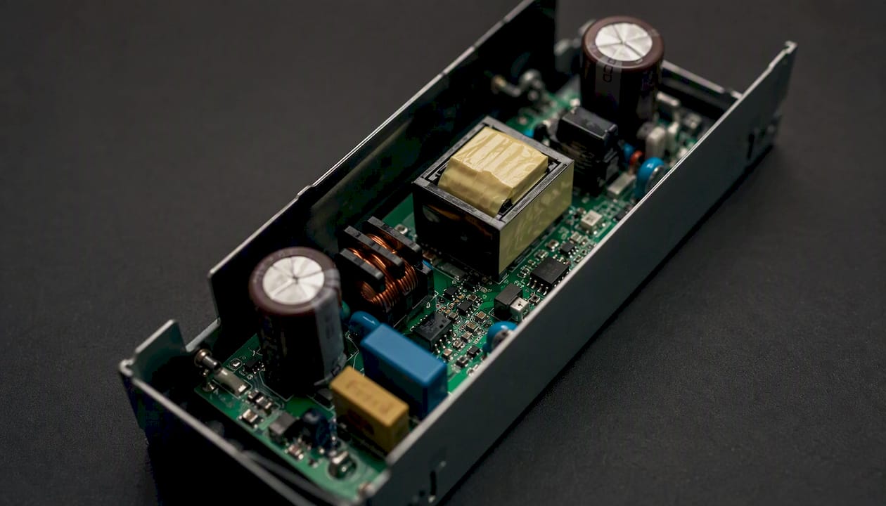
Typical CC applications include COB downlights, high-power single-emitter modules, linear LED fixtures with series-wired LED strings, and many commercial high-bay luminaires. If you are selecting a driver for a Crystorama Foster LED wall mount or a similar integrated fixture, the fixture’s spec sheet will tell you whether the internal LED board is current-driven.
Constant-voltage (CV) drivers
A CV driver holds output voltage steady at a declared value such as 12 VDC or 24 VDC and allows current to vary up to a rated maximum. LED strip tape, modular tape, and many plug-and-play LED fixtures are designed around a fixed supply voltage.
Key distinction: A CV driver going into current limit during a fault or overload will behave like a CC source at that moment. Bench supplies demonstrate this mode-switching behavior clearly, which is why commissioning with a bench supply helps you understand how your driver will respond under abnormal loads before permanent installation.
Practical CV applications: 12V or 24V LED strip runs in coves and under-cabinet lighting, modular LED panels with onboard current regulation, and landscape path lighting. For outdoor CV drivers, an IP65 or IP67 rating is the baseline for Canadian installations exposed to rain or snow.
Which dimming protocol does your driver support?
Drivers may be non-dimmable or support one or more dimming protocols. The common methods are TRIAC (leading-edge and trailing-edge), 0–10V analog, DALI digital, PWM, and DMX, and each has a distinct wiring topology and control ecosystem.
Protocol quick reference:
- TRIAC / forward-phase (leading-edge): Cuts the AC waveform at the leading edge. Common in residential retrofits because it works with many existing wall dimmers. Requires the driver to be TRIAC-compatible; mismatches cause flicker or buzzing.
- Trailing-edge (reverse-phase / ELV): Smoother waveform cut, preferred for LED and electronic loads. Lower minimum load requirements than leading-edge. Specify trailing-edge dimmers with trailing-edge-compatible drivers.
- 0–10V analog: A low-voltage control signal (0–10 VDC) varies driver output. Standard in commercial and institutional lighting. Requires a separate two-wire control run alongside the power wiring.
- DALI (Digital Addressable Lighting Interface): Two-wire digital bus; each driver has an address and can be individually controlled or grouped. Standard in larger commercial projects and building automation systems in Canada.
- PWM: The driver modulates output at a fixed frequency; duty cycle sets brightness. Common in RGB/RGBW strip controllers and some architectural drivers. Frequency matters: below roughly 1,000 Hz, PWM flicker can be visible on camera or to sensitive observers.
- DMX512: Entertainment and architectural standard. Useful for color-mixing and theatrical applications. Requires a DMX controller and proper termination.
Compatibility checklist before you order:
- Confirm the driver datasheet lists your intended dim method under “dimming type” or “control input.”
- Check the minimum load: some TRIAC drivers require a minimum wattage to regulate correctly.
- Verify leading vs. trailing-edge compatibility with the wall dimmer’s spec sheet.
- For 0–10V, confirm whether the driver sources or sinks the control current (most sink).
- Bench-test the driver and dimmer together under realistic load before commissioning a full installation — minimum-load and inrush behavior are frequent real-world failure points.
Flicker is almost always a dimming mismatch, not a failed driver. Swap the dimmer first before replacing the driver.
How do driver topologies affect efficiency and reliability?
Switch-mode power supplies — buck, boost, buck-boost, and flyback — are the standard topologies for LED drivers because they convert input power efficiently rather than burning excess energy as heat. Simple resistor limiting or linear regulators still appear in indicator LEDs and very low-power applications, but they are impractical above a few watts.
Vendor selection guides document these topology tradeoffs in detail, including the protection features that determine long-term reliability.
Protection features to confirm on any driver datasheet:
- OCP (over-current protection): Limits output current during a short or overload.
- OVP (over-voltage protection): Shuts down if output voltage exceeds a safe threshold.
- OLP (open-load protection): Protects the driver when the LED string is disconnected.
- TSD (thermal shutdown): Cuts output if the driver’s internal temperature exceeds a safe limit.
- PFC (power factor correction): Keeps power factor above 0.9 on mains-connected drivers, required for commercial installations in many Canadian jurisdictions.
Pro Tip: For a streetlight or commercial high-bay, choose an isolated flyback CC driver. Isolation provides a safety barrier between mains and the low-voltage LED circuit, and flyback topologies handle the wide input voltage range (90–305 VAC) common in Canadian commercial feeds. A small 12V LED strip in a residential cove needs none of that complexity — a non-isolated buck CV supply is lighter, cheaper, and perfectly adequate.
What datasheet specs should you check before buying a driver?
Start with these fields on every driver datasheet before placing an order.
Decisive checklist:
- Output type: CC or CV — must match the LED module’s requirement.
- Iout (CC) or Vout (CV): Confirm the value matches the LED spec exactly; for CC, check whether the output current is fixed or adjustable.
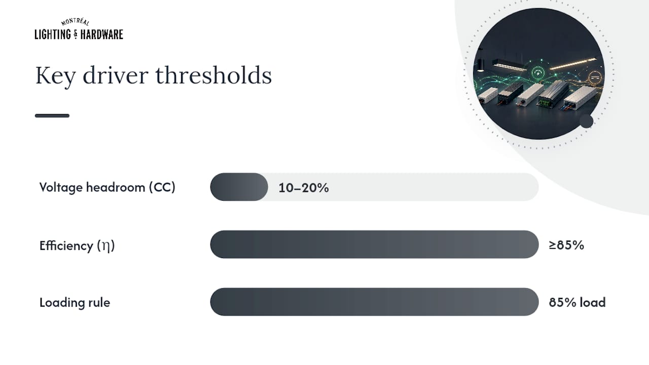
- Output voltage range (CC drivers): Must span the LED string’s total forward voltage with 10–20% overhead.
- Max output wattage: Must exceed your total LED load after applying the 85% loading rule.
- Efficiency typically ranges from moderate to high depending on topology (η): Higher efficiency means less heat in the driver housing. Look for ≥85% at full load.
- Power factor (PF): Commercial installations typically require PF ≥ 0.9.
- Inrush current: High inrush can trip breakers or damage wiring on cold start; check against your circuit’s breaker rating.
- Protections: OCP, OVP, OLP, TSD — all four should be present on any driver above 10 W.
- IP rating: IP20 for dry indoor enclosures; IP65 minimum for damp or outdoor locations; IP67 for direct water exposure.
- Ambient temperature range: Most drivers are rated to 40°C or 50°C; derate output above that threshold.
- Approvals: CSA or ULc marking for Canadian installations.
Manufacturer selection guides list these exact fields — drive current options, voltage ranges, IP ratings, channel counts, and dimming features — making them the fastest way to cross-check a driver against your project requirements.
Reading voltage range on a CC driver: If your LED string’s total forward voltage is 36 V, choose a CC driver whose Vout range comfortably spans that value with headroom, such as 25–50 VDC. A string running near the driver’s maximum Vout risks instability as LEDs warm up and their forward voltage shifts.
Canadian approvals note: Look for the CSA mark (a stylized “C” with an “S” inside) or the ULc mark on the driver label or in the datasheet’s certifications field. These marks confirm the driver has been tested to Canadian standards and will satisfy electrical inspection under the CEC. Drivers must carry CSA or ULc marks for Canadian installation compliance.
How do you size a driver correctly?
Step-by-step sizing procedure:
- Gather LED specs: Collect the forward voltage (Vf), drive current (If), and wattage for each LED or LED module in the circuit.
- Calculate total load: For a CC string, sum the forward voltages of all series LEDs (total Vf = Vf per LED × number of LEDs). For a CV system, sum the wattage of all connected LED loads.
- Choose CC or CV: Current-specified LED = CC; voltage-specified LED strip or module = CV.
-
Calculate required driver output:
- CC: Required Vout range must span total Vf with 10–20% overhead; Iout must match the LED’s rated drive current.
- CV: Required Vout = LED strip voltage (12V or 24V); required current = total strip wattage ÷ supply voltage.
- Apply the 85% loading rule: Minimum driver wattage = total LED load ÷ 0.85. A 50 W LED load needs a driver sized above the load to ensure thermal stability.
- Check thermal and IP requirements: Confirm the driver’s ambient temperature rating suits the installation location and that the IP rating matches the environment.
Worked example 1 — CC string of COBs:
Multiple COB LEDs arranged in series with known forward voltage and current requirements. Total forward voltage plus sufficient overhead voltage to accommodate variations. Calculate total power demand and select a driver with higher wattage rating to ensure reliable operation.
Worked example 2 — CV LED strip run:
For a 24 VDC LED strip run with known wattage per meter and total length, choose a CV driver rated above the total wattage demand. For a run this long, use heavier gauge feed conductors or inject power at the midpoint to prevent voltage drop from causing dimming or color shift at the far end.
Pro Tip: Programmable CC drivers let you set output current via DIP switches or a potentiometer, which means one driver SKU can serve multiple COB wattages on the same project. Keep a few programmable units in your kit — they reduce the number of driver part numbers you need to stock.
What installation and thermal factors affect driver lifespan?
The chief installation risks are overheating, moisture ingress, vibration, and incorrect mounting orientation. Address all four before closing up a fixture or enclosure.
Installation checklist:
- Enclosure type: Confirm the driver’s IP rating matches the environment. IP65 suits damp outdoor locations; IP67 is needed for direct spray or temporary immersion. For outdoor ceiling mounts exposed to Canadian winters, IP65 is the practical minimum.
- Ambient temperature: Most drivers derate output above 40°C or 50°C. Check the derating curve in the datasheet and calculate the expected enclosure temperature at peak summer conditions.
- Airflow clearance: Leave at least 25 mm of clearance around the driver body for convective cooling. Mounting a driver flush against foam insulation or inside a sealed junction box without airflow will shorten its life significantly.
- Mounting orientation: Many switch-mode drivers specify a preferred mounting orientation (label up or horizontal) for optimal thermal performance. Follow the datasheet.
- Vibration resistance: Industrial and outdoor applications may need drivers with conformal-coated PCBs or vibration-rated enclosures.
- Wiring and strain relief: Use terminal blocks rather than flying leads where the driver may need replacement. Secure all conductors with proper strain relief to prevent intermittent connections from vibration.
At 100 W, that is 8 W of continuous heat in the enclosure. In a sealed recessed fixture in a Canadian attic space that reaches 55°C in summer, the driver will thermally derate or shut down. Mount the driver outside the insulated cavity whenever possible, or choose a driver with a higher ambient temperature rating.*
For bathroom applications, selecting an IP-rated driver is as important as the fixture finish. The best bathroom vanity lights for Canadian homes pair well with drivers rated for damp locations (IP44 minimum in Zone 2 areas per CEC requirements).
How do you troubleshoot common LED driver problems?
Most field problems trace back to four root causes: mismatched output type, insufficient voltage headroom, dimmer-driver mismatch, or thermal derating. Identify which one applies before replacing any hardware.
Symptom → cause → quick action:
- Flicker at any dim level: Dimming protocol mismatch or minimum-load violation. Swap the dimmer for a known-compatible model first; check the driver’s minimum load spec.
- Flicker only at low dim levels: Trailing-edge vs. leading-edge mismatch, or the driver’s dim range doesn’t extend that low. Confirm the dimmer type and the driver’s minimum dim percentage.
- LEDs not lighting at all: Check Vout with a multimeter. If Vout is zero, the driver may be in OLP mode (open-load protection triggered). Verify all LED connections are secure before suspecting the driver.
- LEDs dim at the far end of a strip: Voltage drop. Measure voltage at the strip’s far end; if it has dropped more than 0.5 V below nominal, inject power at the midpoint or use heavier gauge supply conductors.
- Driver overheating / TSD triggering: Check ambient temperature against the driver’s rating. Improve airflow or relocate the driver outside the fixture cavity.
- Early driver failure: Check inrush current against the circuit breaker rating. Repeated inrush trips can stress the driver’s input capacitors. Also confirm the driver is not running above 85% of rated load continuously.
Always isolate mains power before measuring or replacing a driver, and follow Canadian Electrical Code safety procedures throughout. A bench supply in CC/CV mode is a useful commissioning tool: connect it in place of the driver to confirm the LED load is healthy before reinstalling the permanent driver.
What do Class 1 and Class 2 drivers mean for Canadian installs?
Class 2 drivers limit available circuit power and voltage to reduce shock and fire risk; Class 1 drivers carry no such power-limited protections and must be wired accordingly. This distinction directly affects which wiring methods the CEC permits.
A Class 2 output is limited to 100 VA and 60 VDC (or lower thresholds depending on voltage range), which means the downstream wiring can be run with less stringent protection requirements. In practice, Class 2 CV drivers for 12V or 24V LED strips allow the low-voltage wiring to be run without conduit in many residential applications, and Class 2 circuits may share a raceway with other Class 2 circuits under CEC rules.
Class 1 drivers, used for high-power CC applications like commercial high-bays or streetlights, require the same wiring protections as any other branch circuit: appropriate conduit, conductor sizing, and overcurrent protection.
Canadian code note: CSA markings on a Class 2 driver confirm it has been tested to the power-limited output requirements. Always verify the CSA or ULc marking and the class designation on the driver label before roughing in wiring, because an inspector will check both.
Practical examples:
- A landscape designer specifying a 24 VDC Class 2 CV driver for low-voltage path lighting can run the secondary wiring in direct-burial cable without conduit in many Canadian municipalities, simplifying installation considerably.
- A commercial electrician installing 150 W CC drivers for high-bay LED fixtures must treat the output wiring as a Class 1 circuit, with full conduit and conductor protection.
- For top lighting stores in Canada, understanding Class 1 vs. Class 2 distinctions helps trade customers specify the right driver family from the start.
How do you buy and source LED drivers in Canada?
Prioritize drivers with CSA or ULc markings and full datasheets listing Vout or Iout, all four protection features, and a temperature derating curve. A driver without a complete datasheet is a driver you cannot properly specify.
Canadian approval checklist:
- CSA or ULc marking on the driver label (not just CE or FCC).
- Declared ambient temperature rating and derating curve.
- IP rating stated for the intended environment.
- Inrush current value listed (important for breaker coordination on multi-driver circuits).
- Dimming protocol clearly stated if a dimmable driver is required.
Practical sourcing tips:
- Ask your supplier for wiring diagrams and application notes, not just the spec sheet. Good suppliers provide both.
- Confirm replacement availability before specifying a driver in a commercial project. A driver that goes end-of-life in two years creates a callback problem.
- Check warranty terms: reputable drivers carry a three-to-five-year warranty; shorter warranties on commercial drivers are a quality signal worth noting.
- For pool and outdoor landscape applications, energy-efficient outdoor lighting options illustrate how driver efficiency directly affects long-term operating costs — the same principle applies to any Canadian outdoor installation.

Montreal Lighting & Hardware carries CSA-approved fixtures and can connect trade customers with driver sourcing guidance for both residential and commercial projects. Whether you are specifying a ceiling mount fixture or a full commercial lighting package, the team at Montreal Lighting & Hardware offers trade pricing, fast shipping across Canada, and the product knowledge to match the right driver to your load. Reach out for a trade consultation or browse the full fixture catalog online.
What habits and shortcuts do experienced installers rely on?
Document the driver part number and take installation photos at handover — every time, without exception. When a driver fails two years later and the homeowner calls, that photo is the difference between a five-minute fix and an hour of detective work.
A few trade shortcuts worth building into your workflow:
- Keep a small kit of common driver types on the truck: a 60 W 24 VDC CV driver, a 40 W 700 mA CC driver, and a programmable CC unit covering 350–1,050 mA. Those three cover the majority of residential and light commercial callbacks.
- When commissioning dimmable circuits, always test the driver-dimmer combination under the actual installed load, not a test lamp. Minimum-load behavior and inrush characteristics vary enough between driver families that bench testing with the real fixture matters.
- Label driver channels clearly in multi-channel RGB or tunable-white installs. A small adhesive label on the driver terminal block takes thirty seconds and saves significant time during any future service call.
- On retrofit projects, check whether the existing dimmer is leading-edge or trailing-edge before ordering the replacement driver. Many residential dimmers installed before 2015 are leading-edge TRIAC types, and most modern LED drivers prefer trailing-edge.
Pro Tip: For critical installations — hotel corridors, healthcare facilities, or any space where a lighting failure causes an operational problem — maintain a spare driver policy. Keep one spare driver per driver family on site or in a nearby storeroom. The cost of a spare is trivial compared to an emergency service call.
One more habit that separates good installers from great ones: always photograph the driver label showing the part number, serial number, and approval markings before closing the fixture. That image, filed with the project documentation, is your proof of compliance if an inspector or insurer asks questions later.
Sources
These references are worth bookmarking for datasheet cross-checks, topology selection, and Canadian compliance verification:
- Quick guide to LED drivers
- LED driver — Wikipedia
- What is an LED driver? A complete guide to types and selection — LUMOSMITH
- SGE0003 — LED driver selection guide (Sanken Semiconductor)
- Understanding constant voltage vs constant current (Rohde & Schwarz)
